 En
En

 русский
 Español
 عربى
عربى Deutsch
Can OEM Casting Parts Replace Welded Components?
Industry News-Structural assemblies built from multiple welded parts carry a compromise that is easy to overlook during the design phase and difficult to correct once a production line is established. Each weld joint is a potential stress concentration point, a dimensional variable introduced by the joining process rather than the part geometry, and an additional inspection requirement. When a component that currently consists of four or six welded pieces could instead be produced as a single casting, the engineering case for that substitution is worth examining seriously — not as a universal rule, but as a decision that depends on specific conditions of geometry, volume, material, and structural load. Understanding where that substitution is feasible and where it is not is the core question for engineers and procurement teams evaluating OEM Casting Parts as an alternative to fabricated assemblies.
The Manufacturing Logic Behind the Question
Welding assembles separate formed or cut pieces into a unified structure by fusing material at defined joints. The process is flexible — it can be applied to a wide range of geometries without tooling investment, adjusted during production without retooling, and used at low volumes without penalty. Those characteristics make welding the natural starting point for complex structural parts, particularly during early development phases when the design is still evolving.
Casting fills a cavity with molten metal and allows it to solidify into a near-net-shape part. The geometry is defined by the mold, and the material distributes continuously through the part volume without any joining operations. The part that emerges from the mold is monolithic — it has no seams, no heat-affected zones, and no dimensional discontinuities introduced by assembly. The trade-off is that the mold represents a fixed tooling investment that must be justified by production volume, and the geometry must conform to the constraints of the casting process rather than the unconstrained freedom of weld fabrication.
Why Weld Joints Create Engineering Vulnerability
A weld joint is not simply a material connection — it is a zone where the base material has been heated to near or above its melting point, resolidified in the presence of a filler material, and then cooled at a rate determined by the surrounding thermal mass. That process changes the microstructure of the metal in the heat-affected zone adjacent to the weld. In steels, this can mean localized hardening or softening depending on the alloy composition. In aluminium, it typically means a reduction in the strength of the parent material in the affected zone.
Beyond the metallurgical change, the geometry of a weld joint creates a stress concentration wherever the weld profile transitions to the base material surface. Under cyclic loading — the condition that governs fatigue life in most structural applications — those concentration points are where crack initiation occurs. A properly executed weld on an appropriately designed joint can manage this risk. But the risk is inherent to the joint geometry in a way that does not apply to a continuously formed cast section of equivalent shape.
This is the core structural argument for casting consolidation: a single casting eliminates the joints and their associated stress concentration geometry. The load path through the part is continuous, and the designer has control over wall thickness, fillet radii, and section transitions in a way that weld assembly does not permit.
Can Custom Castings Replace Multiple Welded Components?
The answer is conditional, and the conditions matter more than the general principle.
Replacement is feasible when:
- The welded assembly consists of parts that are geometrically stable — meaning the final form is consistent across production runs and not subject to frequent design revision
- Production volume is sufficient to amortize the tooling investment across enough parts that the per-unit tooling cost becomes acceptable relative to the labor and material cost of the welded alternative
- The geometry of the assembly can be reproduced in a casting without requiring undercuts or internal features that would make the mold unreliable or uneconomical
- The load case is dominated by fatigue or dynamic stress, where the elimination of weld joints provides a measurable structural benefit
- The assembly currently requires post-weld machining to achieve dimensional tolerance, and the casting process can achieve that tolerance more consistently
Replacement is not straightforward when:
- The part volume is low enough that tooling cost cannot be recovered within the expected production run
- The design is actively evolving, and a cast tool would become obsolete before it is amortized
- The part includes large thin-walled sections that exceed the flow-length capability of the intended casting process
- The material specification requires a mechanical property profile that the casting process cannot achieve without post-casting heat treatment that adds cost and complexity
- The assembly includes intentional joints — flanges, serviceable connections, or interfaces with other components — that are functional rather than structural
Hybrid approaches are worth evaluating when:
A multi-part welded assembly may be partially consolidated without full replacement. Three welded pieces might become two castings that bolt together at a serviceable joint, or one complex casting that replaces four parts while retaining a simple bracket as a separate formed piece. The goal is not the minimum part count in isolation — it is the minimum part count that can be produced reliably, inspected efficiently, and assembled without introducing the failures the casting is meant to prevent.
Structural Benefits of Consolidated Casting Design
Elimination of Weld-Induced Failure Modes
The most consistent structural benefit of replacing a welded assembly with a casting is the removal of the weld joint as a potential failure site. Fatigue failures in fabricated assemblies almost always initiate at weld toes, weld roots, or the edges of heat-affected zones. When those features do not exist, the part's fatigue life is governed by the material properties and section geometry — variables that the designer controls — rather than by the weld quality, which varies with operator skill, fixturing accuracy, and the condition of the welding equipment.
Improved Dimensional Consistency
A welded assembly accumulates dimensional variation from each individual piece and each joining operation. Fixture tolerances, thermal distortion during welding, and springback after cooling all contribute to variation that must be absorbed by subsequent machining operations or accepted as product-to-product variability. A casting reproduces the mold geometry with variation controlled by the mold quality and the solidification process, which in a Precision Casting Process can be managed to tolerances that meet or approach those achievable by machining of the welded alternative.
Reduction in Assembly and Inspection Steps
Each welded joint requires a sequence of operations: fit-up, fixturing, welding, post-weld inspection, and often heat treatment or straightening. Eliminating joints eliminates those steps. For a high-volume production program, the labor and cycle time reduction from consolidating eight pieces into two or three castings represents a material reduction in manufacturing cost that must be weighed against the tooling investment.
Internal Geometry That Welding Cannot Produce
Casting enables internal passages, hollow sections, and geometric transitions that welding cannot achieve without additional fabrication steps. An oil passage, a coolant channel, or a weight-reducing hollow section that would require machined tubes and welded plugs in a fabricated part can be cast in place as part of the primary geometry. This is one of the structural and functional advantages that makes casting consolidation attractive beyond the joint-elimination argument alone.
Limitations That Engineering Must Acknowledge
Tooling Investment and Volume Dependency
A casting tool — whether a sand mold, a permanent mold, or a die casting die — represents an upfront cost that must be recovered across the production run. At low volumes, the per-unit tooling contribution can exceed the labor savings from eliminating welded joints. The volume threshold at which casting becomes economical varies by the complexity of the part and the cost of the welding labor it replaces, and that threshold should be calculated explicitly rather than assumed.
Design Constraints Imposed by the Process
Every casting process imposes constraints on the geometry it can produce. Draft angles are required to allow the part to release from the mold. Wall thickness must remain within a range that allows the metal to fill the mold cavity and solidify without shrinkage defects. Sharp internal corners must be replaced by radii that the metal can flow around without cold shuts or misruns. A welded design that was not created with casting in mind will typically require redesign before it can be cast — sometimes minor, sometimes substantial.
Material Property Differences
Cast metals do not always match the mechanical properties of wrought equivalents, particularly in elongation and impact resistance. The casting process introduces microstructural variation between the surface of the part, which cools faster, and the center, which cools more slowly. For structural applications where ductility under impact load is critical, the designer must verify that the cast material specification meets the requirement — not assume that a material designation in a casting context carries the same properties as the same designation in a wrought form.
Post-Casting Machining Requirements
Near-net-shape is not the same as finished. Most structural castings require machining of mating surfaces, bearing bores, threaded holes, and other features where the dimensional and surface quality requirements exceed what the casting process achieves directly. That machining adds cost and must be accounted for in the total cost comparison between a casting and its welded equivalent.
Aluminium, Brass, and the Material Selection Layer
Material selection interacts with the casting substitution decision in ways that affect both the structural outcome and the process choice.
Aluminium Casting Parts are the prevalent choice in automotive and aerospace structural applications where weight reduction is a design objective. Aluminium alloys cast well in both die casting and Precision Casting Processes, achieve good strength-to-weight ratios, and machine efficiently after casting. The material's thermal conductivity also makes it suitable for parts that must manage heat in service — housings, covers, and brackets adjacent to heat-generating components. Where a welded steel assembly is being reconsidered for weight reduction as well as structural consolidation, an aluminium casting replacement addresses both objectives simultaneously.
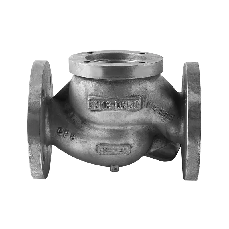
Brass casting parts serve a different application profile: valve bodies, fluid fittings, connectors, and components where corrosion resistance in aqueous or chemical environments is the primary requirement. Brass does not offer the structural weight advantage of aluminium, but it machines to fine tolerances, seals reliably at machined interfaces, and resists corrosion in conditions that would degrade uncoated steel or unprotected aluminium. Casting small metal parts in brass for fluid system applications — where multiple welded or threaded pieces could be replaced by a single cast body — is a well-established substitution pattern in industrial and marine equipment.
The material choice is therefore not independent of the consolidation question. It drives the process selection (die casting for high-volume aluminium parts, precision sand or investment casting for complex geometries or smaller runs), the tooling approach, and the post-casting processing requirements.
Precision Casting Process vs. Die Casting: Which Fits the Consolidation Goal?
These two casting approaches serve different consolidation scenarios, and the choice between them affects the achievable geometry, the dimensional accuracy, the surface quality, and the economics of the substitution.
The Precision Casting Process — encompassing investment casting and related methods — produces complex geometries with thin walls, tight tolerances, and fine surface finish in a single operation. It is well suited to parts with internal passages, complex external profiles, or multi-plane features that die casting cannot accommodate. The process is used across aerospace, medical, and industrial applications where the part complexity justifies the higher per-piece cost relative to die casting. For consolidating a welded assembly that includes curved passages, complex joint geometry, or features at multiple angles, precision casting can reproduce geometry that no other process achieves economically.
Die casting forces molten metal under high pressure into a hardened steel die, producing parts with excellent dimensional repeatability, smooth surfaces, and short cycle times. It is the high-volume process of choice for aluminium and zinc structural parts where the geometry is compatible with the process constraints — consistent wall thickness, adequate draft angles, no significant undercuts. For Casting Parts in Automobile production — brackets, housings, covers, and structural inserts — die casting is the process that makes consolidation economics work at the volumes that automotive programs require.
The distinction matters for the substitution decision because a designer evaluating whether to replace a welded assembly with a casting must choose the process before committing to a design, since the two processes impose different geometric constraints on the final part.
Application Patterns: Where Casting Consolidation Is Established Practice
Automotive Structural Components
The substitution of welded assemblies with integrated castings is documented practice in automotive manufacturing. Engine mounts, suspension brackets, steering knuckles, and transmission housings that once consisted of multiple stamped and welded steel pieces are now produced as single aluminium or iron castings in high-volume programs. The driver is not only the structural argument — it is the combination of weight reduction, assembly simplification, and dimensional consistency that casting consolidation delivers at automotive production volumes. Casting Parts in Automobile programs also benefit from the mature tooling infrastructure and Precision Casting Company networks that have developed around automotive OEM supply chains.
Industrial Frames and Housings
In industrial equipment — pumps, compressors, gearboxes, and structural frames — welded fabrication has historically been used for low-volume custom components where the tooling investment in casting was not justified. As production volumes increase or as designs stabilize, the substitution of welded subassemblies with castings becomes economical. The structural benefit is particularly relevant in equipment subject to vibration, where weld fatigue is a recurring maintenance issue that casting consolidation directly addresses.
Fluid System Components
In hydraulic, pneumatic, and process fluid systems, manifold blocks and valve bodies that were previously assembled from multiple machined and welded pieces are now commonly produced as single castings with machined ports and sealing surfaces. The consolidation eliminates brazed or welded joints within the fluid circuit, which are potential leak points, and allows internal passage geometry that improves flow characteristics relative to drilled or welded passage alternatives.
OEM Casting Parts Manufacturing: What Feasibility Evaluation Requires
Engineering feasibility and manufacturing feasibility are not the same evaluation. A part geometry that is theoretically consolidable into a single casting may present tooling, quality control, or supply chain challenges that affect whether the substitution is practical within a specific production program.
Design for manufacturability (DFM) review with the casting manufacturer is the step that identifies those challenges before tooling is committed. The review evaluates draft angles, wall thickness distribution, parting line placement, gating and riser design, and the dimensional tolerances achievable without post-casting machining. It also identifies features that will require machining regardless of the casting quality, so that machining operations are planned from the outset rather than discovered after the first castings are inspected.
For OEM programs, the DFM review also establishes the inspection plan — which dimensions are held to drawing tolerance, which are monitored for process control, and which functional surfaces require verification at every production run. A Casting Parts Manufacturer with OEM program experience will have standard procedures for this review; a supplier that has not executed OEM casting programs may not.
Prototype castings from the intended production tooling — rather than from temporary sand molds or machined prototypes — provide the most reliable validation of the substitution before full production commits. They confirm that the casting process produces the geometry, the material properties, and the surface condition required, and they reveal any process adjustments needed before production volume begins.
Evaluating Manufacturers and Suppliers for Casting Consolidation Projects
The supplier selection decision for a casting consolidation project differs from a standard casting procurement. The manufacturer must be capable not only of producing the casting but of supporting the DFM process, managing the tooling investment, and maintaining dimensional consistency across a production run that may span years.
Key evaluation criteria include:
Process capability range: Does the manufacturer operate Precision Casting Process lines, die casting lines, or both? The required process depends on the part geometry and volume, and a supplier limited to one process may recommend it regardless of fit.
Material range: Can the supplier cast and certify aluminium, brass, iron, or steel as required by the application? A supplier whose material range does not include the required specification cannot be qualified for that program regardless of other capabilities.
Tooling ownership and control: Who owns the tooling, and what happens to it if the supply relationship changes? This is a commercial question with engineering consequences — tooling that cannot be transferred to another supplier creates a dependency that affects long-term sourcing flexibility.
Inspection and certification infrastructure: For OEM Casting Parts programs, the supplier must maintain dimensional inspection records, material certification documentation, and in some cases process audit capability for customer quality reviews.
China casting parts sourcing: For buyers evaluating China-based supply, the considerations above apply with additional attention to communication protocols, lead time management for tooling revisions, and logistics planning for prototype iterations.
Making the Substitution Decision: A Structured Approach
The decision to replace welded assemblies with castings should follow a sequence that prevents premature commitment at either end — neither tooling investment before the design is stable, nor indefinite deferral of a substitution that would deliver clear structural and economic benefit.
A workable sequence:
- Identify the welded assembly or assemblies under evaluation and document the current part count, joint count, inspection requirements, and per-unit fabrication cost
- Define the structural load case and the failure modes that drive the current design — fatigue, static overload, corrosion, dimensional instability
- Evaluate whether the geometry of the assembly can be cast using the available process options, with the help of a DFM review from a prospective casting manufacturer
- Estimate the tooling cost and the production volume required to recover it, and compare the per-unit casting cost at that volume to the current fabricated assembly cost
- Prototype in the intended production process if the evaluation supports proceeding, and validate structural performance before committing production tooling
Ruian Huazhu Machinery Co., Ltd. supports casting consolidation projects across aluminium, brass, and iron casting applications, with engineering capability that includes DFM review, tooling design support, and OEM program management for automotive, industrial, and fluid system components. For procurement and engineering teams evaluating whether a specific welded assembly can be replaced by a custom casting, engaging the manufacturing team early in the evaluation — before the design is finalized — is the step that determines whether the substitution is achievable within the project's technical and commercial constraints.
Related products
-

The Fully Automatic Core Shooter with Core Pulling is designed to streamline the production process,...
See Details -

The Fully Automatic Environmentally Friendly Core Shooting Machine is a highly advanced, eco-conscio...
See Details -

The fully automatic core shooting machine with lower mold removal is a front-end solution designed t...
See Details -

The Lower Mold Removable Core Shooting Machine is designed to offer high flexibility and reliability...
See Details -

The Hydraulic Fully Automatic Core Shooting Machine is an essential tool in modern casting operation...
See Details -

The environmentally friendly core shooting machine with lower mold removable is a high-performance s...
See Details -

The Lower Mold Removable Type Environmentally Friendly Core Shooting Machine with Door is an advance...
See Details -

The Hydraulic Environmentally Friendly Core Shooting Machine is a front-end technology designed to o...
See Details
![]()
Welcome to our company to design according to your design and sample proofing.
Contact Infor
-
 Haixi Town, Pingyang County, Wenzhou City, Zhejiang Province, China
-
 +86-13868387823
-
 +86-577-65197155
-
 +86-577-65197166
-
 13868387823@139.com
huazhultd@outlook.com
Quick Links
Products
Copyright © Ruian Huazhu Machinery Co., Ltd. All Rights Reserved.

